
Picture a bay at the end of a low-ceiling row. A driver sees a green light, turns in, and finds a car already there. The indicator was visible; the detection behind it was wrong. At that point the question is less about the color of the light than the equipment above the bay, the data it sends, and what the operator expects to learn from it.
When the job is to say free or occupied, start by evaluating an ultrasonic detector. When a vehicle must be tied to a bay record, put a video probe on the shortlist. A beam may block the mount; a camera may have no clear plate view. Test awkward bays before committing to either layout.
What information must each parking bay provide?
Ask the operations team what they will do with each record. A free-bay count helps direct traffic. A plate tied to a bay may help someone find a car or investigate a parking rule. These lead to different hardware and data-handling plans. Our parking guidance system range includes components for both occupancy guidance and more detailed space-level information, but the correct design depends on the site.
An occupancy-only brief can be quite focused. The detector reports whether the bay is free. A controller aggregates that status, and indicators or directional displays guide drivers. Zone counts and an alert for a silent detector are useful additions to an occupancy brief. Put them on the requirements sheet in their own lines. Neither calls for a plate record by default.
If a driver needs to find a parked car by plate, the brief changes. Now the system needs a dependable plate-to-bay match, and the operator must manage the resulting record. Have the site owner and privacy team settle access and retention before cameras appear on every row of the equipment schedule. Otherwise the proposal may collect information nobody has agreed to use.
Write the required outputs before asking for a product quotation. A one-line requirement such as “smart parking sensor” leaves too much room for a proposal that looks good on paper yet answers the wrong operating question.
How do ultrasonic and video probes produce different records?
An ultrasonic detector measures distance to what sits below it and converts that reading into bay occupancy. On the TGW-T01Q ultrasonic detector page, we describe ultrasonic status detection, local processing, data communication, and red/green LED indication. Its listed mounting and communication details are specific to TGW-T01Q. Keep that model sheet beside the drawing; a different detector may send data or mount differently.
The practical output is a status event. The system can count free spaces and update signs without storing a plate for each occupied bay. This makes sense when the operator’s main goal is to direct drivers and measure availability. It does not, by itself, answer “where did this particular car park?”
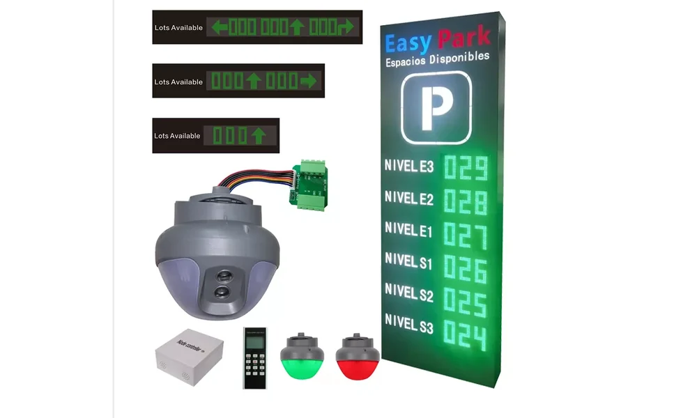
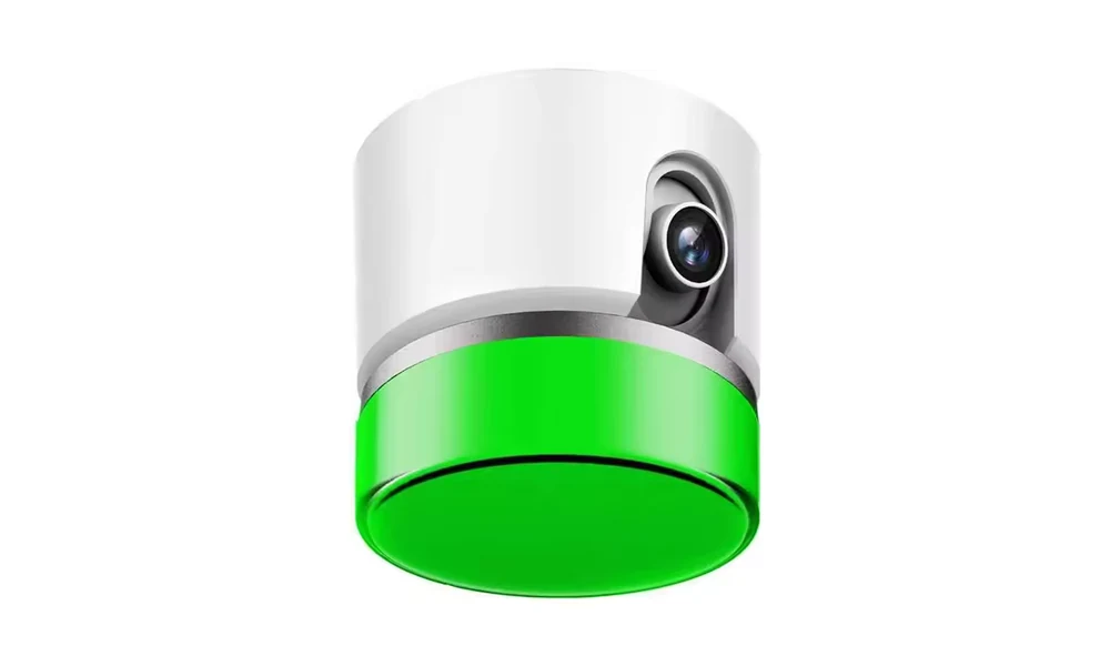
إن TGW-5803 video probe adds a camera and recognition path. It can report bay occupancy and a plate result when the view supports one. That last condition matters. Ask the designer to mark the camera view on the plan and show sample captures from the site. The count of bays assigned to a probe should come from that layout, not from a generic camera-to-bay ratio.
Neither product category earns a universal accuracy ranking here. Mounting height, obstructions, parked position and light can all change what a selected unit sees. A pilot with recorded arrivals and departures will tell the project team more than a broad performance claim.
| Design question | Ultrasonic occupancy detection | Video occupancy and plate detection |
| Primary record | Free or occupied bay | Bay status, with a possible plate record |
| Site view to confirm | Detector position above the intended bay, clear measurement path | Camera angle, lighting and visibility of the vehicle and plate |
| Data design | Status communication to controllers and signs | Image-derived events and the agreed network and record policy |
| Good starting brief | “Show accurate availability by bay and zone” | “Link the parked vehicle to a bay where the site needs that record” |
The table identifies the first decision. The drawing and model-specific quotation settle the installation.
Which garage conditions can rule out a sensor layout?
The sensor must observe the same bay named in the software. Walk the row and look up. A sprinkler, pipe or beam may sit exactly over the printed bay center. Note that clash on the plan, along with ramps, pillars and tight turns. The open middle row is rarely the best place to judge the whole garage.
With ultrasonic detection, the measurement path matters as much as the device name. The TGW-T01Q page calls for placement relative to the space center and a clear path. If a front-mounted or split arrangement is proposed instead, redraw the indicator and cable route. The original ceiling mark may no longer make sense.
For video, inspect the view with a vehicle parked, not just an empty painted rectangle. A high vehicle or a car in the next bay can hide the plate from a camera that seemed well aimed during the survey. Return under the lighting used after dark, if the garage operates then, and keep sample captures from the difficult spaces.
The indicator is part of the layout too. Our article on LED parking space indicators explains the driver-facing signal. In this selection exercise, confirm that a driver approaching the aisle can see the light early enough to make a safe turn. If the sensor works but the indicator is hidden by a beam, the guidance experience still fails.
Power and communication should be drawn on the same plan as the devices. Record ceiling access, cable tray availability, controller location, network coverage, and the route to floor or entrance displays. Product pages describe different links for different components. Ask for a proposed topology for the chosen models, with the party responsible for each connection named.
What should your pilot bay prove before rollout?
A pilot built around the easiest bay proves little. Include an ordinary space, then choose the places the installer is most likely to question: a column-side bay, a crowded ceiling, a dark corner or a turning area. The actual set should reflect the garage, not a fixed sample template.
For each bay, define a pass condition before the test. Park and leave with the vehicle types the garage normally handles. Observe the local indicator, the zone display and the management record. Record the time and any mismatch, then repeat after changing vehicle position within the bay. For video, inspect whether the plate result belongs to the correct bay and whether the site’s record rules are followed. For ultrasonic, check that neighbouring movement does not change the selected bay’s status.
| Pilot check | Expected result to define | Evidence to keep |
| Vehicle enters and leaves | Correct bay status after each event | Timestamped screen and bay photo |
| Adjacent bay changes | No false change on the tested bay | Paired bay observations |
| Driver-facing indication | Light and direction display agree with bay status | Approach-view photo and display record |
| Network interruption and recovery | Behaviour matches the approved design | Event log and recovery note |
| Plate-to-bay match, if specified | Correct vehicle record for the intended bay | Access-controlled test record |
Keep the pilot record as an acceptance record. If a bay fails, note what changed—the bracket position, camera angle, configuration or detector—and repeat that bay’s test. A successful retest is more useful than a general claim about accuracy.
What should go into the detector RFQ?
An RFQ is easier to answer when the plan carries the awkward details. Mark the bay count, traffic direction, floor height, overhead clashes, lighting and available power and network routes. Show where a driver should see a free-space signal. On a separate line, say whether the operator needs only occupancy, zone counts or a plate-to-bay match. Name any existing parking platform and the person responsible for its interface.
For each proposed model, request a device list and a marked topology showing the detector, indicator, controller, display, power and data connections. Ask for a separate detail of the exceptional bays. A single standard-bay sketch cannot resolve the column-side space that caused the survey question. Confirm privacy and retention responsibilities with the operator when video records are in scope.
We can review the plan against our ultrasonic and video guidance products. To make that review useful, contact our project team with the bay layout, ceiling and lighting notes, existing infrastructure, and the data your operation truly needs. The result should be a testable layout for this garage, not a generic sensor preference.